I am an architect in a design build firm in the US taking some time to see if PlusSpec is a good option for our design and precon workflow. I have worked for the last 15 years in revit…
I am giving myself a practice project to model a one room structure with custom elements and document a set of construction drawings in layout. My first hurdle is making a custom wall that is
3/4” cedar cladding over
Benjamin Obdyke Hydrogap over
7/16” OSB sheathing over
2x6 studs 16” OC with
1/2” painted drywall on the interior
I am struggling to create this wall. I read that I need to use the multi-skin wall type, which has masonry as the outer layer. How do I swap out the masonry material options for wall cladding options? If I edit the tag of that layer to 19C_Cladding, it just recategorizes that masonry material.
On a related note, it would be great if any layer could be any material, and if I could add and subtract layers as I need them, the same way revit builds walls. Or perhaps that is possible, but I don’t know how yet?
I would use the light weight multi skin wall option, from there you can create custom claddings for the cedar, the OSB sheathing or Rigid air barrier we call it here in NZ, Hydrogap, the studs and the drywall interior lining as well as the insulation in the walls. Here in NZ we are required to put all ext claddings on a cavity batten min 20mm, you can define the vert or horiz batten to the inside or outside of the wall in the framing section. You can also customise you battens as well.
The recommendation @Sekta mentioned is also what I would recommend doing to create the wall type you’re after.
Currently wall layers cannot be added or subtracted from walls, however below are a few methods that can achieve this.
Method 1
Creating materials & using the Edit Tag & BOQ Category feature (located below each material field) to adjust the material info, the layers of each wall type can be adjusted to suit most wall types. You’ll just need to select the wall type that’s closest to the wall type you’re trying to create.
Method 2
Use the Wall Surface Tool to add the additional layers to each wall.
Method 3
Draw multiple walls together so that they are overlaid or “stacked”.
Notes:
You may need to use parts of Method 1 in some instances to get the desired outcome.
Windows & doors would only be placed in one of the walls, so you’ll need to create the additional openings in the other walls (using the “none” option) & likely recess the windows using the Recess Window field.
Thank you to you both for responding! Its cool to interact with designers in different parts of the world.
I achieved the wall assembly I wanted with the lightweight multiskin wall type, thank you.
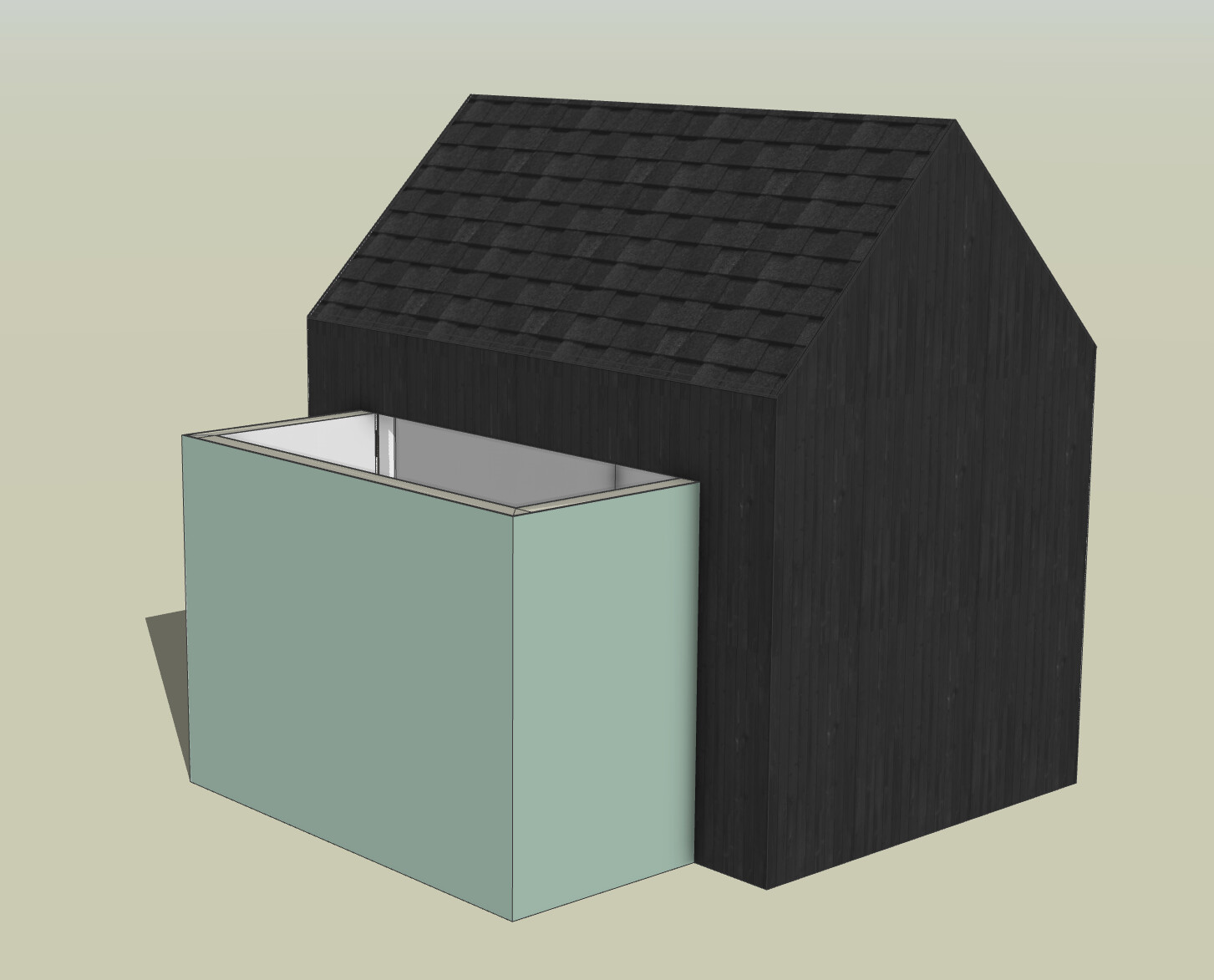
I am making a main gable volume and a small flat roof bump out. I read somewhere that to make the space inside contiguous, I should make a door opening that spans from one side of the bump out to the other. but the walls do not join, so you can see the wall ends instead of seeing the drywall wrap around the corner. is there a better way to do this?
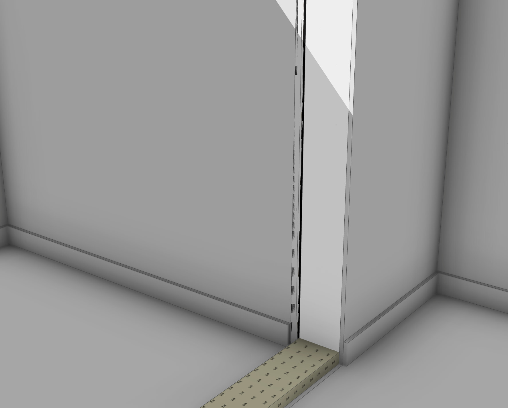
Additionally, when I edited the wall to have it trim the bottom plate at doors it did not update accordingly. And the base trim is tagged as 24G_FIX_OUT_A in the wall settings, but it is modeled as untagged, so I can’t easily hide it.
Thanks for your help as I learn this powerful tool!
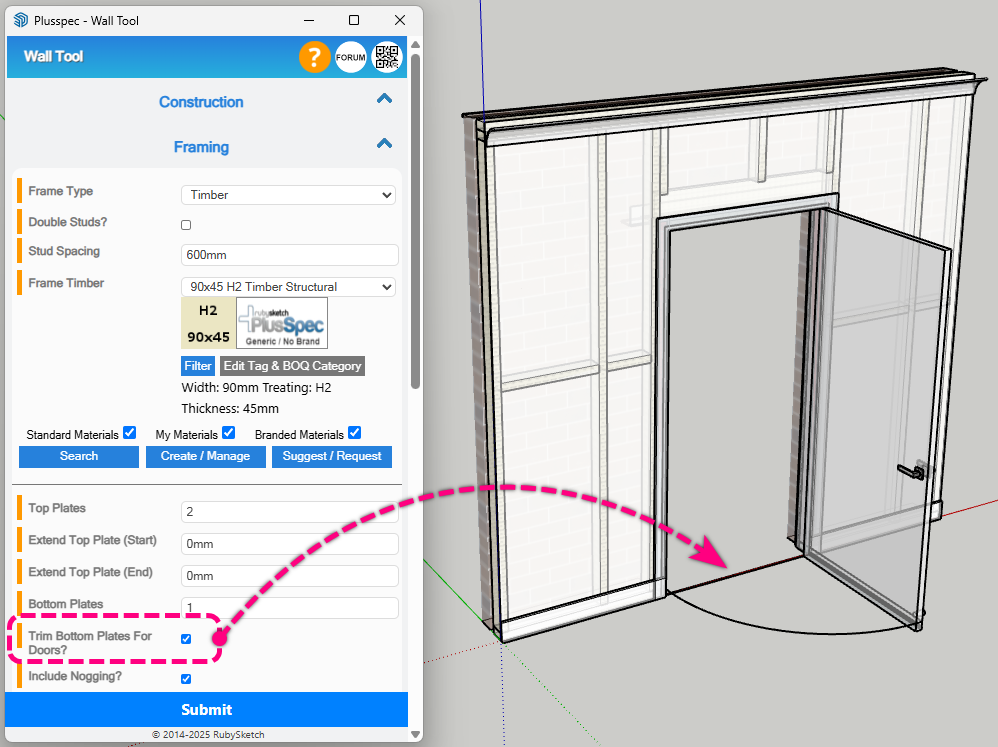
There is a check box to remove the bottom plate under the door but i can’t remember where it is because i turn the “17a” frame" tag off as i like the plate to be quantified in my BOQ / estimate.
Fyi its easier to create scenes and click on the struct off scene do you funny see the game when walking through. . @Grant where is the tick box?
Thanks @Andrew. Still unsure of the best way to make a section of a structure have shorter walls but have it be a contiguous space on the inside. Any tips?
The way you mentioned is one of the methods we’d recommend. To clean up the result, I would recommend drawing small return walls where the outcropped walls join back into the adjacent walls & then deleting these walls. This will result in a “corner” being added to the end of the outcropped walls, which can then be aligned with the adjacent walls to give the continuous look.
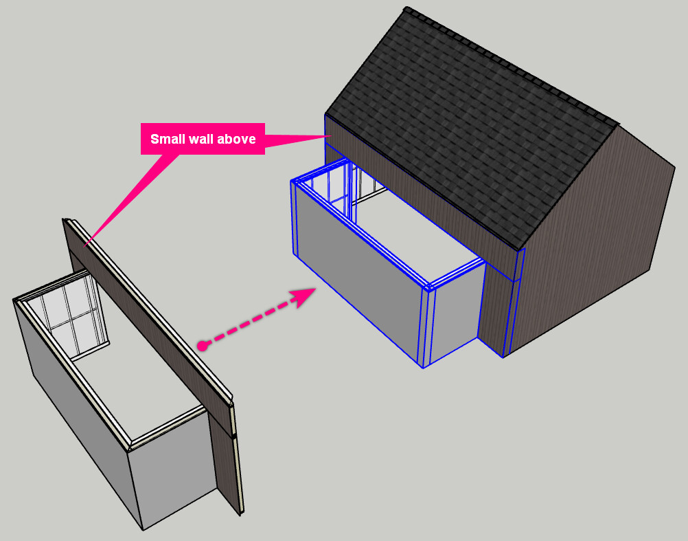
Another method I would recommend is to draw all the walls along that side of the building at the same height & then add a small wall above them (like shown in the image below). Note: Make sure to do the same steps mentioned above to add corners to each end of the smaller wall placed above. Also, change the Header Height to a small value greater than 0 (e.g. 1mm).
In response to what @Andrew was saying, the tickbox is located within the Framing section of the Wall Tool (shown in the image below). The section of bottom plate within the door will be placed on the 17A_FRAME(CUT) tag, so you can adjust its visibility via the Tags section of the Default Tray.
Thanks! I tried both methods. I didn’t like that the second method - making the walls the same height, then making another short wall above makes a line in the model that creates visual noise while modeling, and potentially more clean up/work arounds in layout, but it does seem like a more powerful option. I am struggling with how much clean up needs to happen when you make changes to the model. I have not found ways to attach assemblies to each other like you can in Revit, so if I want to move that gable end wall two feet over, the opening moves with it, and the floor, roof, structure, and foundation wall below do not move. I also have not found a way to redraw the outlines of elements (another nice revit feature) so I have to fix or redraw all of these elements.
Regarding the horizontal line in the walls, it’s placed on the Wall Linework tag so you can toggle it’s visibility via the Tag Manager, so there shouldn’t be anything to clean up in Layout. You’ll just need to turn the tag off for the desired scenes & update each scene.
The issue you mentioned currently will only happen when moving one end of the wall or adjacent walls (i.e. the starting end, which should be the righthand side is viewing from the external side of the wall). To navigate this, follow these steps:
Use the Split Wall Tool to add a split in the adjacent walls somewhere between the first window/door & the adjoining corner (I’d suggest halfway as a rule of thumb). The wall will now be split in two walls. Note: If moving the wall back towards the adjacent walls, make sure the split is positioned far enough away from the corner to allow for the new position of the moved wall.
Use the Push/Pull Wall Tool to move the wall to the desired position.
Select both walls on one side fo the moved wall (i.e. the result of Step 1), then right-click on them & select + WALLS > Wall Operations > Meld Walls. The two walls will now be joined back together as one wall.
Repeat Step 3 for the opposite side of the moved wall.