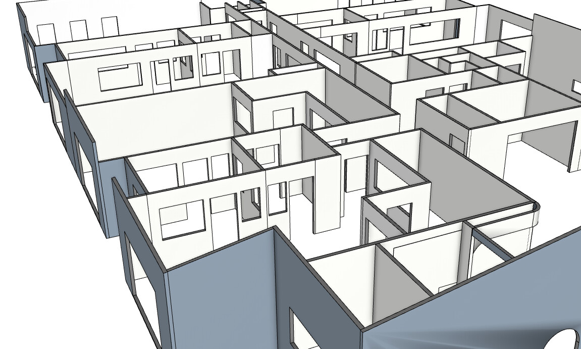
I’m working with an IFC floor plan imported into SketchUp and want to use PlusSpec Pro to create timber framed walls (90x45 @ 450 centers, Queensland residential spec).
I’ve got the Wall Tool dialog set up correctly, but when I tried tracing the walls manually, I found it incredibly frustrating. I couldn’t get the tracing to work properly and kept making mistakes.
Is manual tracing the only way to do this, or is there an automated method to convert the IFC wall geometry into PlusSpec Pro framed walls?
Also - is struggling with the manual tracing normal, or am I doing something wrong? Should I be snapping to specific points, or tracing centerlines vs edges?
Another issue: When I go into “Structure” view in the BIM model, there’s nothing inside - the walls are empty. Why is that? When I imported the IFC, I thought I specified what studs to use during import. Shouldn’t the structural framing already be there?
There are two ways to draw walls, which I’ve listed below. The second option may be useful for what you’re trying to achieve.
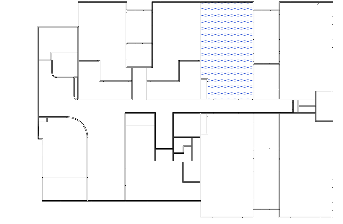
Manually drawing the walls, which include tracing over plans or other geometry. Dimensions can also bve entered when drawing walls to get them the accurate lengths. The draw points can also be changed (more info on this below).
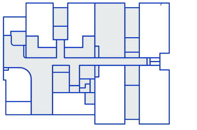
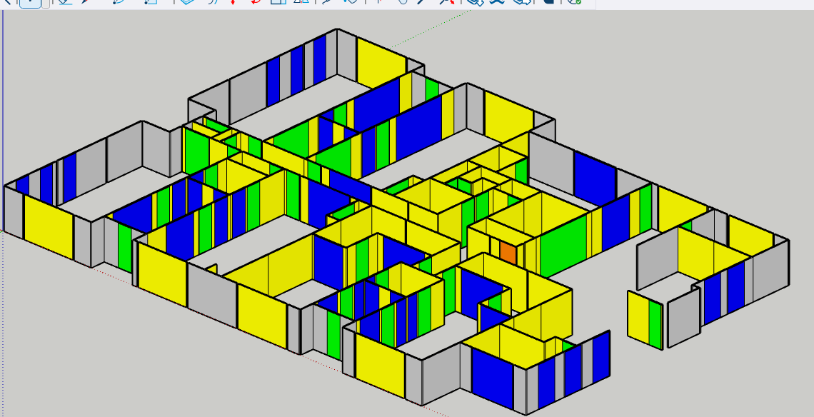
Using the new “walls from face” feature, which located in the right click menu under + WALLS when a face is selected. This will draw the walls around the selected face &/or edges from the pitching point of the walls.
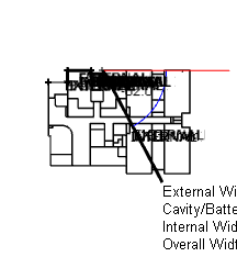
The walls will always draw from the side of a “skin” (never centerpoints) so I would trace around the geometry or plan according to where you want to align the wall (i.e. change the draw point to the outermost draw point if you’re tracing around the outermost points of the geometry/plan). The draw point & direction of walls can be adjusted by using the following shorcuts.
Right arrow = Cycles through the different draw points of the wall (e.g. pitching point, external side, internal side, etc.).
INSERT/down arrow = Flips the drawing direction (clockwise is the default ).
The reason the wall framing isn’t appearing is because it’s currently only available for the PlusArchitect & PlusDesignBuild versions (you’re using Pro). If you’d like to find out more about these products & upgrade to get acces to more features, I’ve added links to each of them below. You can also contact support@plusspec.com for more info.
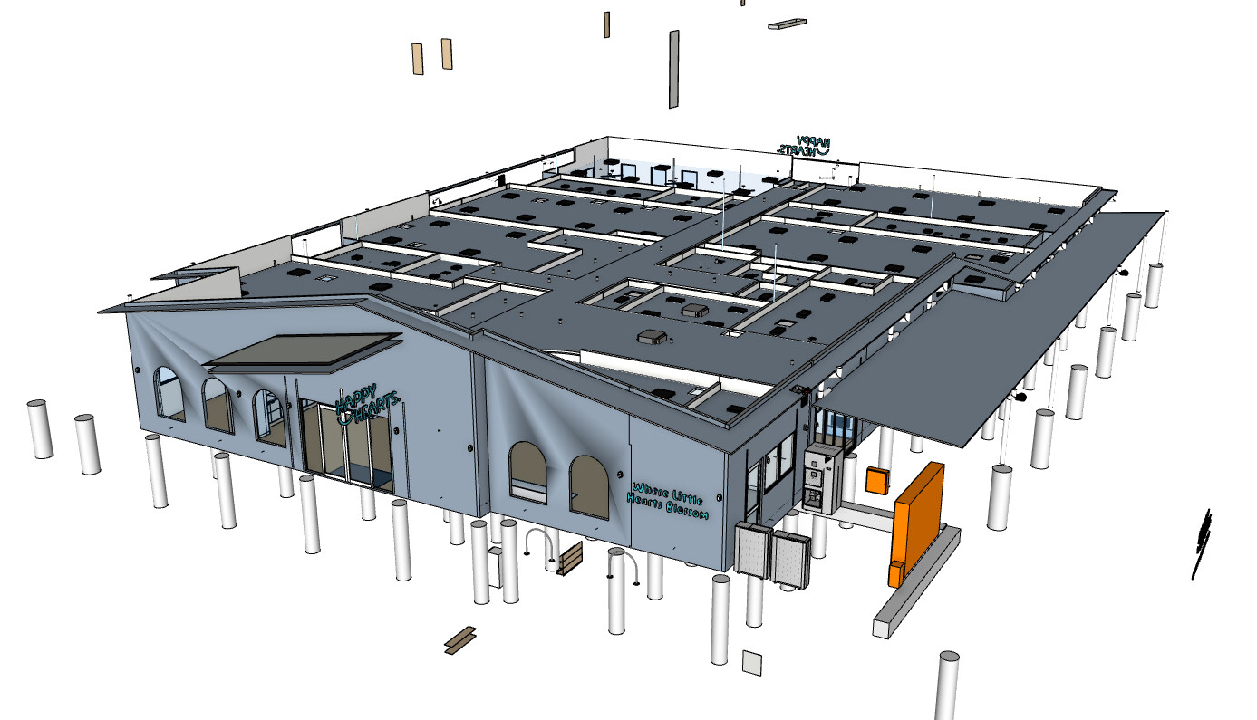
Hi Grant, I recently was importing a file from my roof and frame design program into via ruby console and in a few short clicks I got this back….Is this something i can use to input doors windows and walls?
Hi Jim.
PlusDesignBuild will import and quantify IFC geometry and you can manually alter the geometry by breaking into the groups or components to create window and for opening, all be it slow. You can then use the custom window and door tools to add quantifiable elements.
Personally i would create a face and use the new create walls from face option. I would cut section through the geometry and “create group from from slice” using the right click menu. This will make the walls easier to trace.
Jim as you move forward i would look at creating vignettes of typical vindictive types according to your preferences and local building codes. We are testing and implementing new features that’ll help you create similar walls from face. We are working on AI wall creation yet everything we have so far is not ready for betac testing.
In hope this helps. I’m in my phone without my glasses so i hopefully the typos aren’t to inhibiting.